
Product description
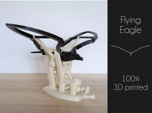
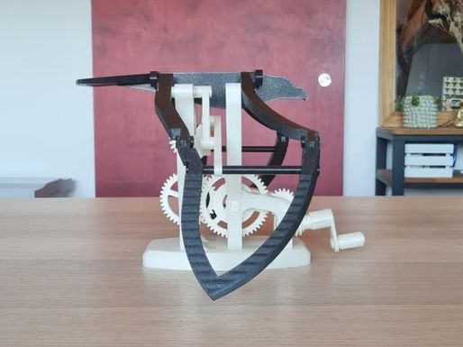
This is my entry for the “mechanial marvel” contest, I designed this model specifically for the contest.

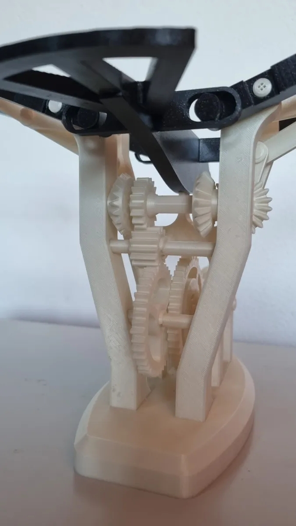
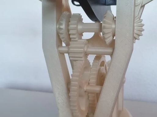
The mechanism is 100% 3d printed, no need for bolts and nuts, and all the pieces snap on together, so no need for glue either. This means that you can disassemble any piece in case it breaks or if I update something (some parts do require some force to assemble though).
The tolerances are quite tight on some part to have the least amount of play in the mechanism.
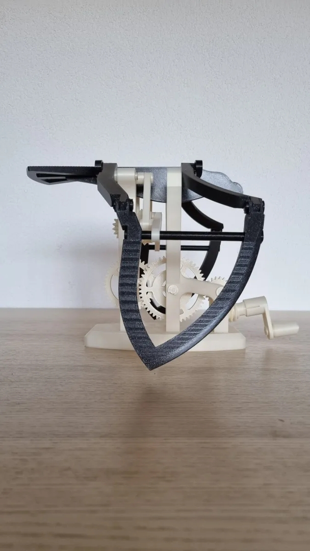
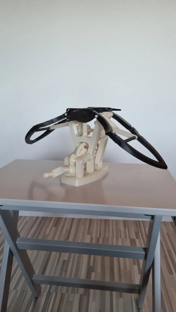
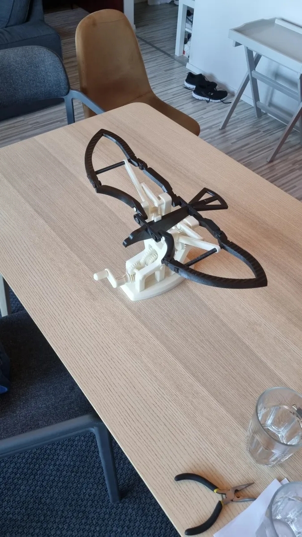
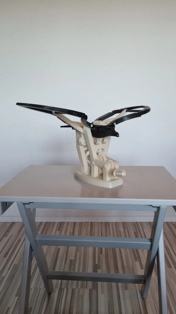
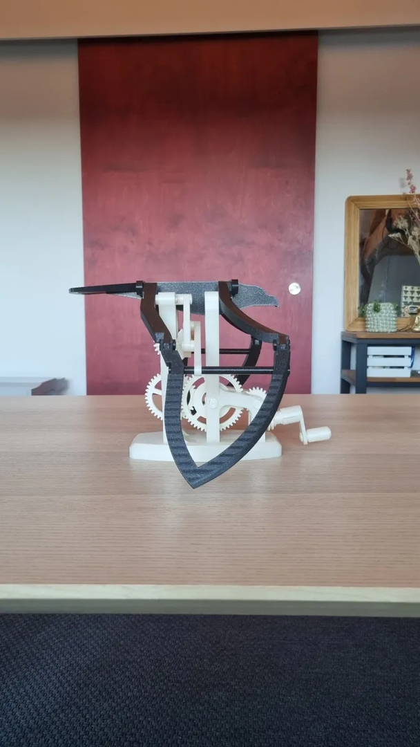
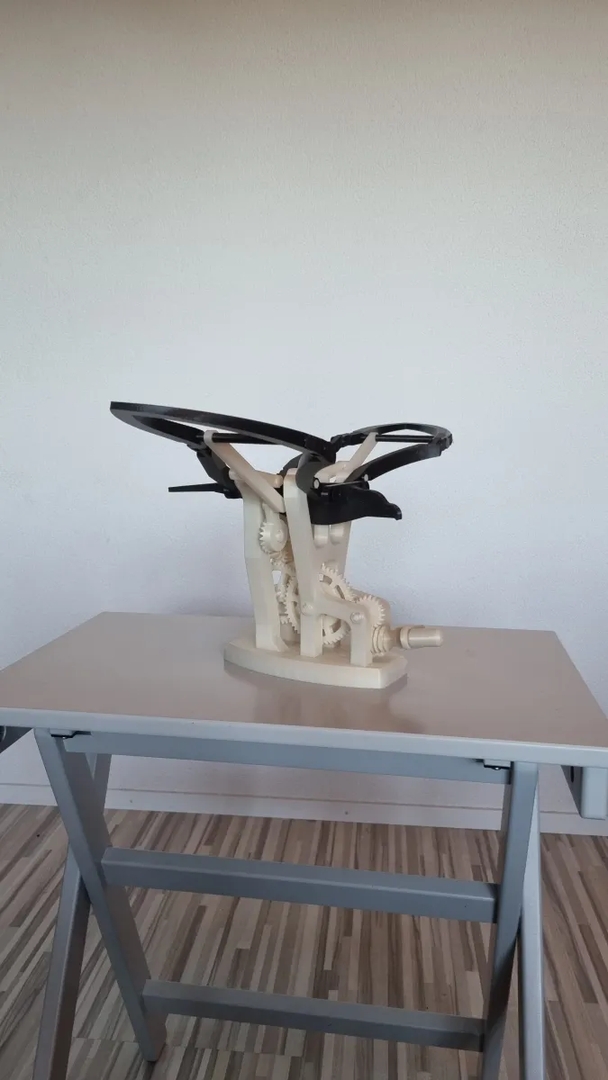
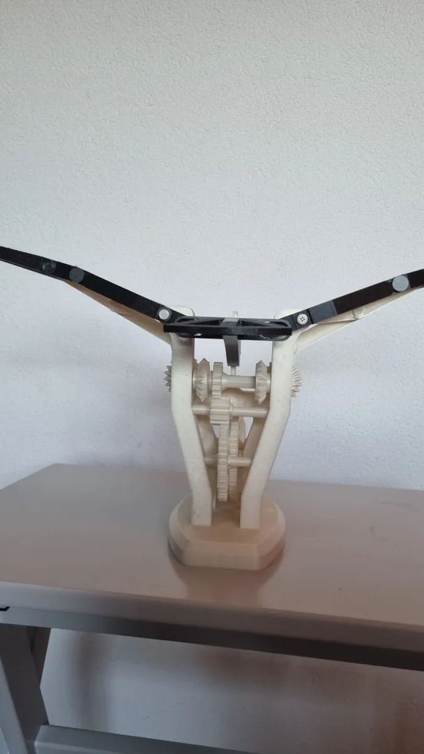
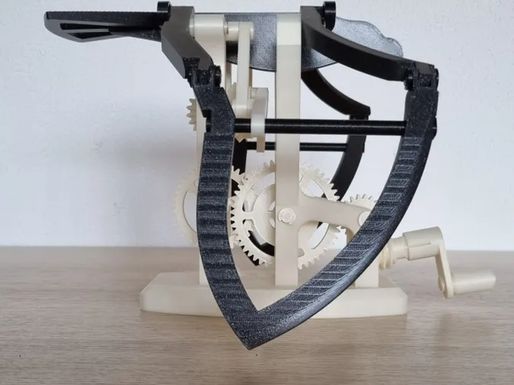
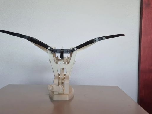
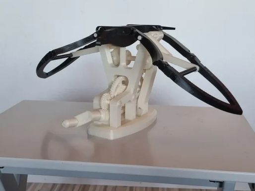
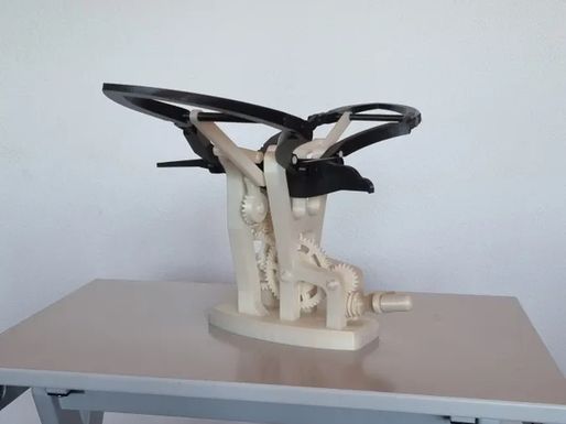
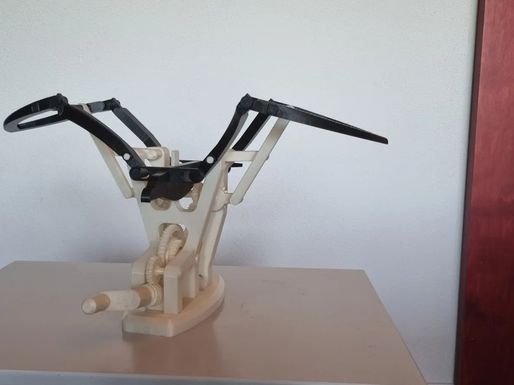
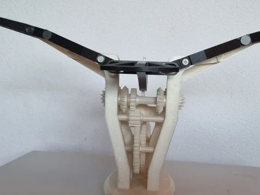
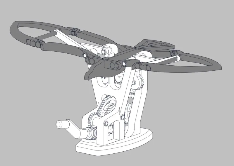
It is an automaton of a flying eagle operated with a crank. I wanted to reproduce as best as I could the motion of an eagle flapping its wings, so I designed this mechanism around the Chebyshev lambda linkage :

I was inspired by some other automatons using this linkage but never for flapping wings, so I thought it could be a good challenge. And to be even more challenging, I tried to do it 100% 3d printed and with no glue, only snap on connexions.
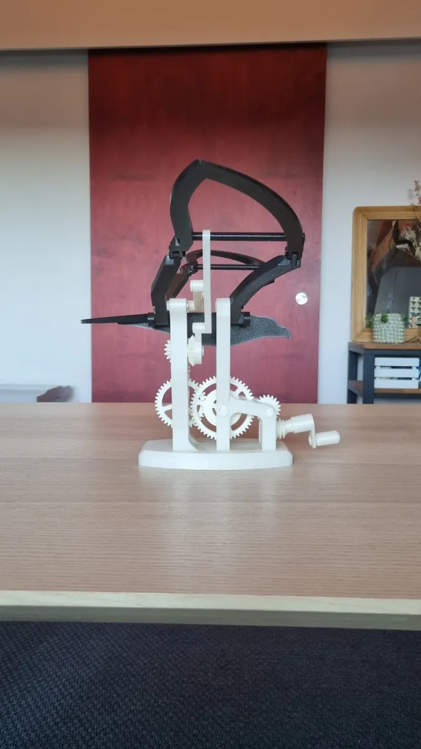
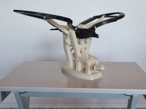
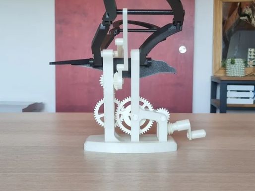
The mechanism uses two Chebyshev lambda linkages, one for each wing. A gear train is used to transfer the motion back to the crank with a worm gear at the end to be able to lock the position of the eagle (the worm gear prevents the motion from going backwards, meaning that the weight of the wings will not drive the crank).
This is a long and challenging build, I don't expect everyone to nail it first try, but it is extremely rewarding to have it working at the end.
It took quite long to design, test and print (72 pieces), so it might not be completely perfect when I publish it. But given the deadline of the contest I had to do things quickly. I only managed to print one copy of the eagle, but I will probably update the model as I already see some things I can improve.
Printing settings
Print every part form the folder “Individual parts”, some of them must be printed multiple times, the number of time each part must be printed is noted on the file note.
They are a total of 72 pieces to print for the whole mechanism.
I printed all the parts in PLA with standard prusa slicer profile with 0.2mm layer height.
For all the axles I recommend an infill of 50% or higher because they are the part that take all of the load (I even took it up to 90% infill for the longest axles).
No part requires support.
All the STL files are in their printed orientation.
Assembly :
1 - Base front assembly
| connect base_front with the base The parts should snap on together and not move anymore | 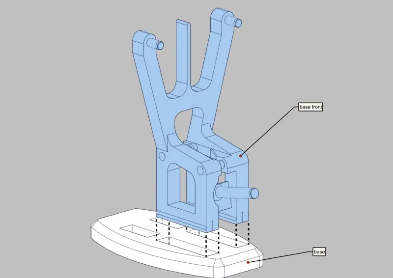 |
| Place the 2 gears in their dedicated spot and align them with the holes. | 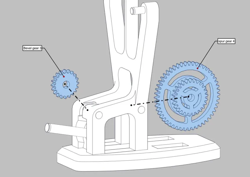 |
| Insert the two 60mm axles to secure the gears. | 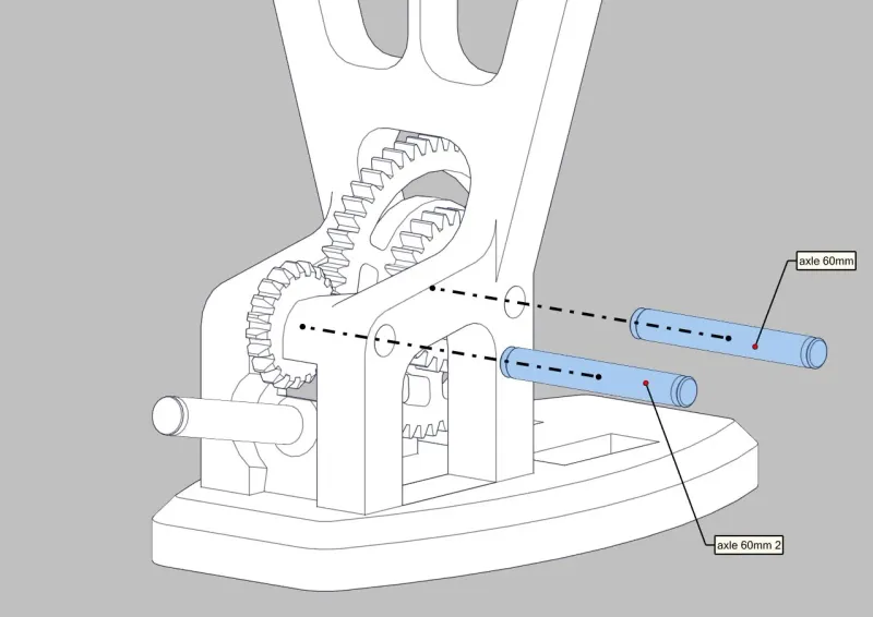 |
| Lock the axle in place with two 8mm clips at the end of each axle | 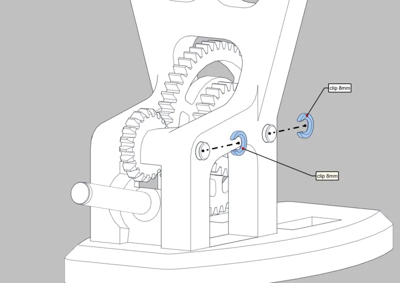 |
| Place the worm gear on the shaft and lock it with a 10mm clip. Insert the crank above the worm gear, it should snap on in only 1 orientation. | 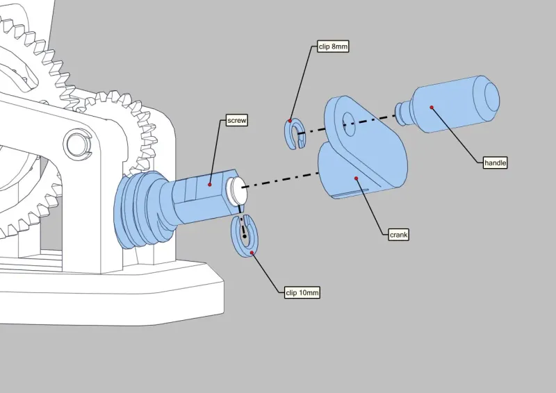 |
2 - Base left and right
| spur gear sub-assembly Assemble the 3 axles with the 3 gears, the 2 round axles are locked in place with a 8mm clip each and the hexagonal one has a 10mm clip | 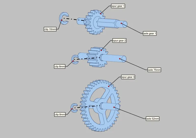 |
| Bevel gear orientation Place the 2 bevel gear at each end of the hexagonal axle. The groove on the inside should be aligned on both gear (pointing up on the picture) to have a synchronized motion. | 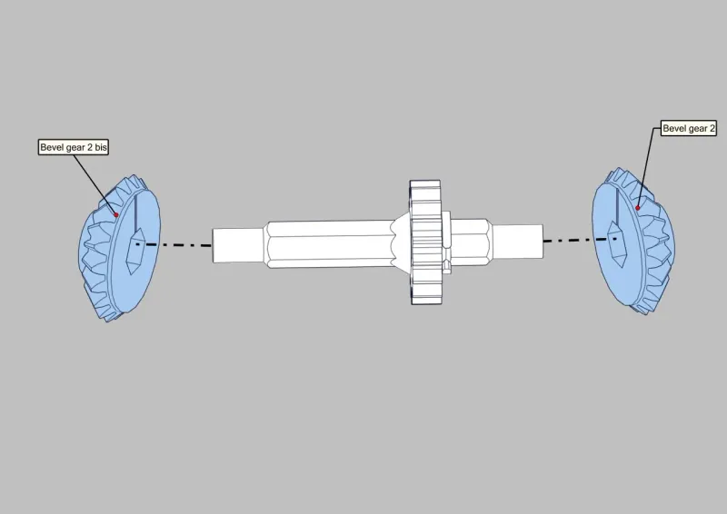 |
Connect the 3 sub-assemblies with the 2 bases Make sure to have the axles in the right orientation. All the gears must be on the left side of the assembly when looking from behind (see the picture for reference) | 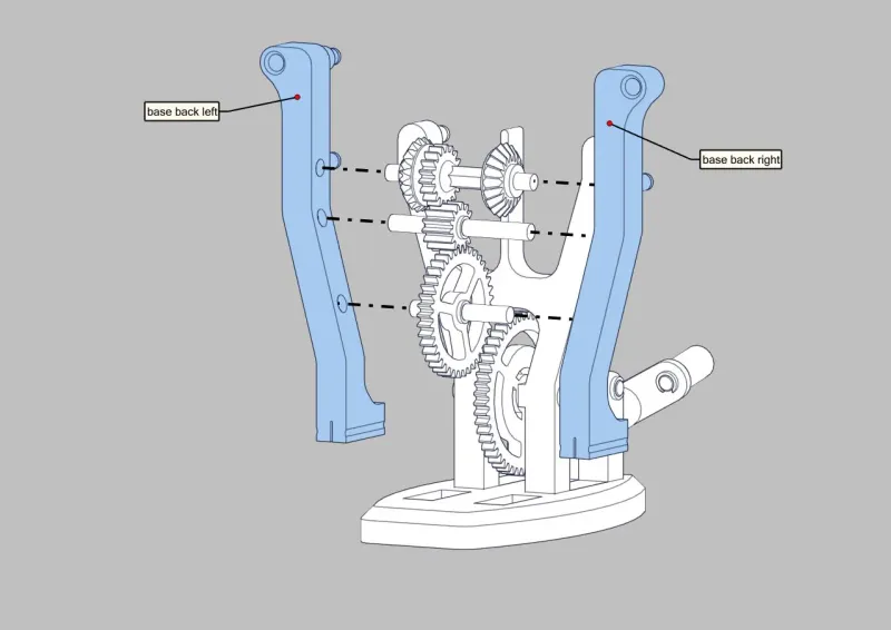 |
Connect the assembly with the base, it should snap in place. Here you can try to turn the crank to see if everything moves correctly. | 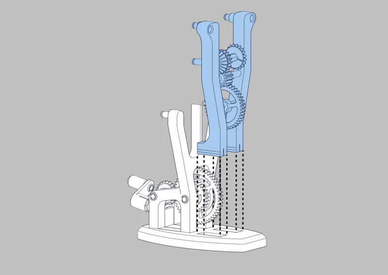 |
| Assemble both Chebyshev lambda linkage with 8mm clips | 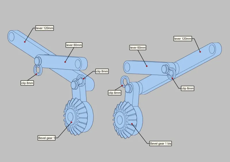 |
| Place both assemblies on the base, and lock them in place with 8mm clips. | 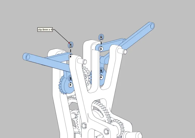 |
bevel gear 2 orientation
| 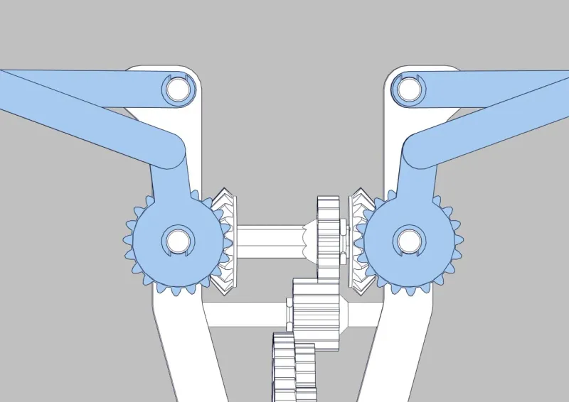 |
3 - Eagle assembly
Put the body on the base_front, it should be able to slide up and down smoothly, sand if necessary. Connect the tail, it snaps in the back of the body. | 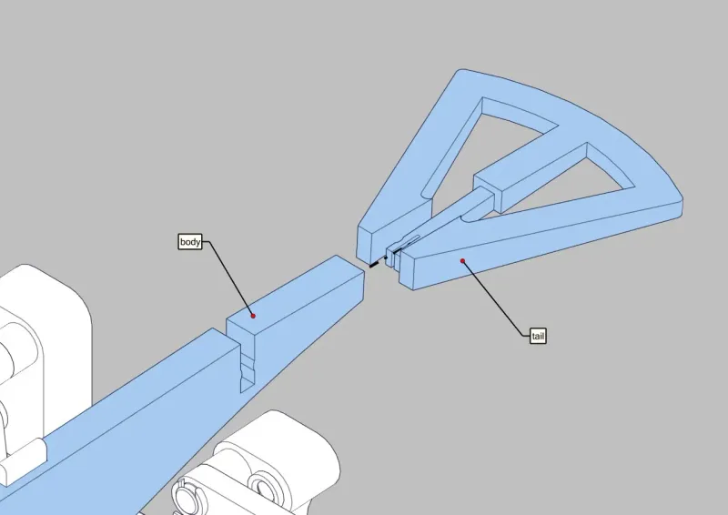 |
| Assemble the base of the wings on the front_base. | 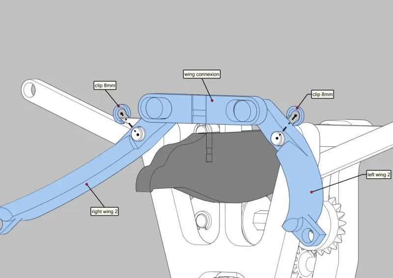 |
| Once the assembly is complete you can clip the wing connexion in the body (this might require some force) | 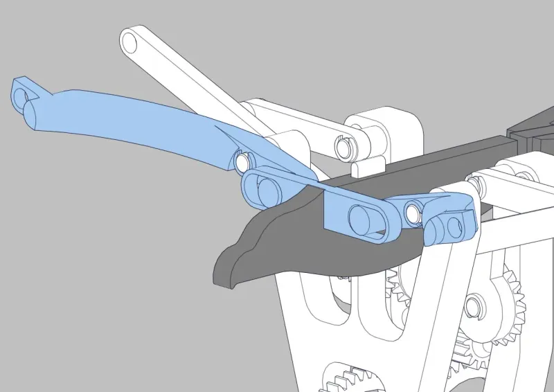 |
Do the same thing on the other side, this time you need to add the two 35mm axles. Make sure not to invert the two pieces left wing 1 and right wing 1. | 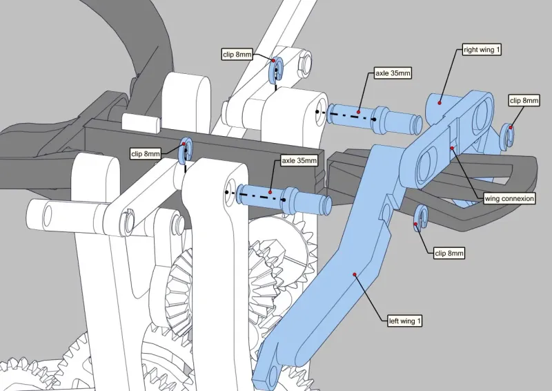 |
| Same thing as the other side, snap the wing connexion in the body once the assembly is completed. | 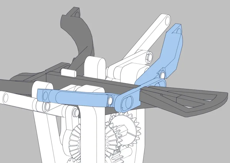 |
Connect the tip of each wing (be carefull not to invert both wing tips as it might not work otherwise) Make sure that the wings can move nice and smooth, sand if necessary. The tip can rotate only down, if not, the parts are mixed up. | 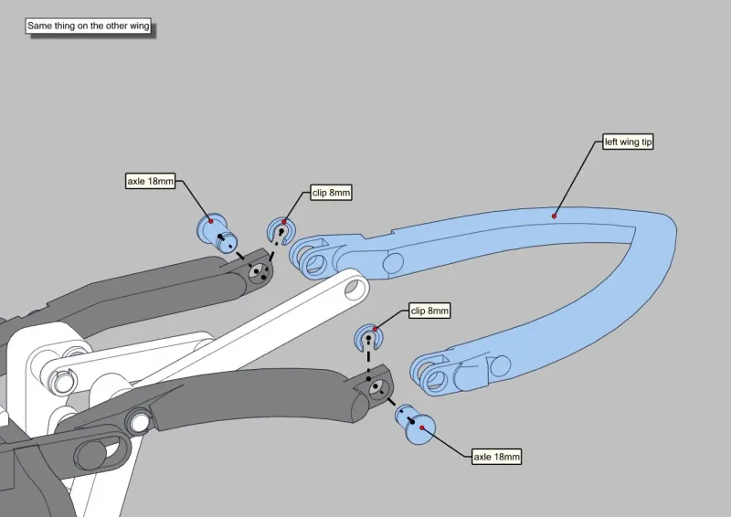 |
Finally connect the 115mm axles on each wing, it goes through the Chebyshev lambda linkage. I highly reccommend to lubricate the worm gear to reduce friction and have a smooth rotation (I used the grease provided with the MK3 printer). | 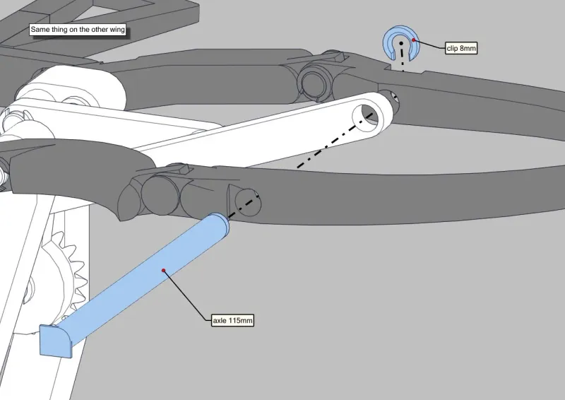 |
Once everything is assembled, the mechanism should work by turning the crank clockwise.
If it requires too much force to turn the crank, don't force or you might break an axle. You can sand the pivots or use some lubricant. Mine runs very smoothly after just lubricating the worm gear.
Tips :
Make sure that every pivot and moving part can move smoothly before assembly, especially the pivots of the wings and the body that slides up and down on the base.
I highly reccommend to lubricate the worm gear to reduce friction and have a smooth rotation (I used the grease provided with the MK3 printer).
Update to come :
I am not totally happy with the way the wings come down, they kind of fall due to the slack in the gears. I can fix this problem by adding some friction to the wing's pivots but I don't have time now to design and test a solution so I will do it later.
Tags
License
❌ Sharing without ATTRIBUTION
✔️ Remix Culture allowed
❌ Commercial Use
❌ Free Cultural Works
❌ Meets Open Definition
This work is licensed under a Creative Commons (4.0 International License) Attribution—Noncommercial—Share Alike
https://creativecommons.org/licenses/by-nc-sa/4.0/
All files (2)
Details parameters
<p>Print every part form the folder “Individual parts”, some of them must be printed multiple times, the number of time each part must be printed is noted on the file note.<br>They are a total of 72 pieces to print for the whole mechanism.</p><p>I printed all the parts in PLA with standard prusa slicer profile with 0.2mm layer height.</p><p>For all the axles I recommend an infill of 50% or higher because they are the part that take all of the load (I even took it up to 90% infill for the longest axles).</p><p>No part requires support.</p><p>All the STL files are in their printed orientation.</p><h3><strong>Assembly :</strong></h3><h4><strong>1 - Base front assembly</strong></h4><figure class="table" style="width:714px;"><table style="border:1px double var(--input-border);"><tbody><tr><td style="border:1px solid rgb(191, 191, 191);padding:0.4em;vertical-align:top;">connect base_front with the base<br><br>The parts should snap on together and not move anymore</td><td style="border:1px solid rgb(191, 191, 191);padding:0.4em;vertical-align:top;"><figure class="image"><img style="aspect-ratio:800/566;" src="https://media.printables.com/media/prints/286080/rich_content/f6607ca4-b4c1-49bd-b0c5-eed807ab1670/thumbs/cover/800x566/jpg/eagle-assembly_front-base-assembly.webp" width="800" height="566"></figure></td></tr><tr><td style="border:1px solid rgb(191, 191, 191);padding:0.4em;vertical-align:top;">Place the 2 gears in their dedicated spot and align them with the holes.</td><td style="border:1px solid rgb(191, 191, 191);padding:0.4em;vertical-align:top;"><figure class="image"><img style="aspect-ratio:800/566;" src="https://media.printables.com/media/prints/286080/rich_content/3101387c-e82c-4d04-add1-674e2626f081/thumbs/cover/800x566/jpg/eagle-assembly_view-2.webp" width="800" height="566"></figure></td></tr><tr><td style="border:1px solid rgb(191, 191, 191);padding:0.4em;vertical-align:top;">Insert the two 60mm axles to secure the gears.</td><td style="border:1px solid rgb(191, 191, 191);padding:0.4em;vertical-align:top;"><figure class="image"><img style="aspect-ratio:800/566;" src="https://media.printables.com/media/prints/286080/rich_content/631991b2-20e8-4101-a546-bdd6b68cc570/thumbs/cover/800x566/jpg/eagle-assembly_view-3.webp" width="800" height="566"></figure></td></tr><tr><td style="border:1px solid rgb(191, 191, 191);padding:0.4em;vertical-align:top;">Lock the axle in place with two 8mm clips at the end of each axle</td><td style="border:1px solid rgb(191, 191, 191);padding:0.4em;vertical-align:top;"><figure class="image"><img style="aspect-ratio:800/566;" src="https://media.printables.com/media/prints/286080/rich_content/4487596c-d502-4a10-9a7d-24eead4a9567/thumbs/cover/800x566/jpg/eagle-assembly_view-4.webp" width="800" height="566"></figure></td></tr><tr><td style="border:1px solid rgb(191, 191, 191);padding:0.4em;vertical-align:top;">Place the worm gear on the shaft and lock it with a 10mm clip.<br>Insert the crank above the worm gear, it should snap on in only 1 orientation.</td><td style="border:1px solid rgb(191, 191, 191);padding:0.4em;vertical-align:top;"><figure class="image"><img style="aspect-ratio:800/566;" src="https://media.printables.com/media/prints/286080/rich_content/1172836d-9433-4b53-835f-9c59606cef13/thumbs/cover/800x566/jpg/eagle-assembly_view-5.webp" width="800" height="566"></figure></td></tr></tbody></table></figure><h4><strong>2 - Base left and right</strong></h4><figure class="table" style="width:714px;"><table style="border:1px double var(--input-border);"><tbody><tr><td style="border:1px solid rgb(191, 191, 191);padding:0.4em;vertical-align:top;">spur gear sub-assembly<br><br>Assemble the 3 axles with the 3 gears, the 2 round axles are locked in place with a 8mm clip each and the hexagonal one has a 10mm clip</td><td style="border:1px solid rgb(191, 191, 191);padding:0.4em;vertical-align:top;"><figure class="image"><img style="aspect-ratio:800/566;" src="https://media.printables.com/media/prints/286080/rich_content/bea1c549-2655-4eae-afc1-6bea8533e5ac/thumbs/cover/800x566/jpg/eagle-assembly_view-6.webp" width="800" height="566"></figure></td></tr><tr><td style="border:1px solid rgb(191, 191, 191);padding:0.4em;vertical-align:top;">Bevel gear orientation<br><br>Place the 2 bevel gear at each end of the hexagonal axle.<br>The groove on the inside should be aligned on both gear (pointing up on the picture) to have a synchronized motion.</td><td style="border:1px solid rgb(191, 191, 191);padding:0.4em;vertical-align:top;"><figure class="image"><img style="aspect-ratio:800/566;" src="https://media.printables.com/media/prints/286080/rich_content/a11ea8a7-1fd1-4eaf-bc48-3cedb95b58bb/thumbs/cover/800x566/jpg/eagle-assembly_view-7.webp" width="800" height="566"></figure></td></tr><tr><td style="border:1px solid rgb(191, 191, 191);padding:0.4em;vertical-align:top;"><p>Connect the 3 sub-assemblies with the 2 bases</p><p>Make sure to have the axles in the right orientation. All the gears must be on the left side of the assembly when looking from behind (see the picture for reference)</p></td><td style="border:1px solid rgb(191, 191, 191);padding:0.4em;vertical-align:top;"><figure class="image"><img style="aspect-ratio:800/566;" src="https://media.printables.com/media/prints/286080/rich_content/40e2d18f-09b8-4c66-bc61-e540caba593e/thumbs/cover/800x566/jpg/eagle-assembly_view-8.webp" width="800" height="566"></figure></td></tr><tr><td style="border:1px solid rgb(191, 191, 191);padding:0.4em;vertical-align:top;"><p>Connect the assembly with the base, it should snap in place.</p><p>Here you can try to turn the crank to see if everything moves correctly.</p></td><td style="border:1px solid rgb(191, 191, 191);padding:0.4em;vertical-align:top;"><figure class="image"><img style="aspect-ratio:800/566;" src="https://media.printables.com/media/prints/286080/rich_content/425b1b05-13a3-4514-8630-ba40ba66a547/thumbs/cover/800x566/jpg/eagle-assembly_view-9.webp" width="800" height="566"></figure></td></tr><tr><td style="border:1px solid rgb(191, 191, 191);padding:0.4em;vertical-align:top;">Assemble both Chebyshev lambda linkage with 8mm clips</td><td style="border:1px solid rgb(191, 191, 191);padding:0.4em;vertical-align:top;"><figure class="image"><img style="aspect-ratio:800/566;" src="https://media.printables.com/media/prints/286080/rich_content/7ee9690e-7b15-4f79-920c-c8358732cf9c/thumbs/cover/800x566/jpg/eagle-assembly_view-13.webp" width="800" height="566"></figure></td></tr><tr><td style="border:1px solid rgb(191, 191, 191);padding:0.4em;vertical-align:top;">Place both assemblies on the base, and lock them in place with 8mm clips.</td><td style="border:1px solid rgb(191, 191, 191);padding:0.4em;vertical-align:top;"><figure class="image"><img style="aspect-ratio:800/566;" src="https://media.printables.com/media/prints/286080/rich_content/940565b5-818a-4233-b5be-fb81d09636d8/thumbs/cover/800x566/jpg/eagle-assembly_view-10.webp" width="800" height="566"></figure></td></tr><tr><td style="border:1px solid rgb(191, 191, 191);padding:0.4em;vertical-align:top;"><p>bevel gear 2 orientation<br><br>Make sure that both side are perfectly symetrical before putting on the clips.</p><p> </p></td><td style="border:1px solid rgb(191, 191, 191);padding:0.4em;vertical-align:top;"><figure class="image"><img style="aspect-ratio:800/566;" src="https://media.printables.com/media/prints/286080/rich_content/c551e466-49c8-424a-8a31-fa27cd6fdc9b/thumbs/cover/800x566/jpg/eagle-assembly_view-11.webp" width="800" height="566"></figure></td></tr></tbody></table></figure><h4><strong>3 - Eagle assembly</strong></h4><figure class="table" style="width:714px;"><table style="border:1px double var(--input-border);"><tbody><tr><td style="border:1px solid rgb(191, 191, 191);padding:0.4em;vertical-align:top;"><p>Put the body on the base_front, it should be able to slide up and down smoothly, sand if necessary.</p><p>Connect the tail, it snaps in the back of the body.</p></td><td style="border:1px solid rgb(191, 191, 191);padding:0.4em;vertical-align:top;"><figure class="image"><img style="aspect-ratio:800/566;" src="https://media.printables.com/media/prints/286080/rich_content/6d474f81-aa7e-4844-ba74-20088535b5de/thumbs/cover/800x566/jpg/eagle-assembly_view-12.webp" width="800" height="566"></figure></td></tr><tr><td style="border:1px solid rgb(191, 191, 191);padding:0.4em;vertical-align:top;">Assemble the base of the wings on the front_base.</td><td style="border:1px solid rgb(191, 191, 191);padding:0.4em;vertical-align:top;"><figure class="image"><img style="aspect-ratio:800/566;" src="https://media.printables.com/media/prints/286080/rich_content/58d720b6-faeb-4b61-87c0-a292121afb8b/thumbs/cover/800x566/jpg/eagle-assembly_view-14.webp" width="800" height="566"></figure></td></tr><tr><td style="border:1px solid rgb(191, 191, 191);padding:0.4em;vertical-align:top;">Once the assembly is complete you can clip the wing connexion in the body (this might require some force)</td><td style="border:1px solid rgb(191, 191, 191);padding:0.4em;vertical-align:top;"><figure class="image"><img style="aspect-ratio:800/566;" src="https://media.printables.com/media/prints/286080/rich_content/19213d60-1e54-427b-8fbd-0b3dae289773/thumbs/cover/800x566/jpg/eagle-assembly_view-15.webp" width="800" height="566"></figure></td></tr><tr><td style="border:1px solid rgb(191, 191, 191);padding:0.4em;vertical-align:top;"><p>Do the same thing on the other side, this time you need to add the two 35mm axles.</p><p>Make sure not to invert the two pieces left wing 1 and right wing 1.</p></td><td style="border:1px solid rgb(191, 191, 191);padding:0.4em;vertical-align:top;"><figure class="image"><img style="aspect-ratio:800/566;" src="https://media.printables.com/media/prints/286080/rich_content/4f426cfd-e09d-4ac3-a014-a9f60bc99155/thumbs/cover/800x566/jpg/eagle-assembly_view-16.webp" width="800" height="566"></figure></td></tr><tr><td style="border:1px solid rgb(191, 191, 191);padding:0.4em;vertical-align:top;">Same thing as the other side, snap the wing connexion in the body once the assembly is completed.</td><td style="border:1px solid rgb(191, 191, 191);padding:0.4em;vertical-align:top;"><figure class="image"><img style="aspect-ratio:800/566;" src="https://media.printables.com/media/prints/286080/rich_content/7001e5c1-6ad2-442e-8639-284430cba669/thumbs/cover/800x566/jpg/eagle-assembly_view-17.webp" width="800" height="566"></figure></td></tr><tr><td style="border:1px solid rgb(191, 191, 191);padding:0.4em;vertical-align:top;"><p>Connect the tip of each wing (be carefull not to invert both wing tips as it might not work otherwise)</p><p>Make sure that the wings can move nice and smooth, sand if necessary.</p><p>The tip can rotate only down, if not, the parts are mixed up.</p></td><td style="border:1px solid rgb(191, 191, 191);padding:0.4em;vertical-align:top;"><figure class="image"><img style="aspect-ratio:800/566;" src="https://media.printables.com/media/prints/286080/rich_content/f1867966-b684-4222-bf47-faaae560e62f/thumbs/cover/800x566/jpg/eagle-assembly_view-18.webp" width="800" height="566"></figure></td></tr><tr><td style="border:1px solid rgb(191, 191, 191);padding:0.4em;vertical-align:top;"><p>Finally connect the 115mm axles on each wing, it goes through the Chebyshev lambda linkage.<br> </p><p>I highly reccommend to lubricate the worm gear to reduce friction and have a smooth rotation (I used the grease provided with the MK3 printer).</p></td><td style="border:1px solid rgb(191, 191, 191);padding:0.4em;vertical-align:top;"><figure class="image"><img style="aspect-ratio:800/566;" src="https://media.printables.com/media/prints/286080/rich_content/edba6ea9-e20d-4924-b132-4eef21b6a2e6/thumbs/cover/800x566/jpg/eagle-assembly_view-19.webp" width="800" height="566"></figure></td></tr></tbody></table></figure><figure class="image"><img style="aspect-ratio:800/566;" src="https://media.printables.com/media/prints/286080/rich_content/2f876c0e-99f5-427a-97ca-a4c173ccee4f/thumbs/cover/800x566/jpg/eagle-assembly_view-20.webp" width="800" height="566"></figure><p>Once everything is assembled, the mechanism should work by turning the crank clockwise.</p><p>If it requires too much force to turn the crank, don't force or you might break an axle. You can sand the pivots or use some lubricant. Mine runs very smoothly after just lubricating the worm gear.</p><p> </p><h4><strong>Tips :</strong></h4><p>Make sure that every pivot and moving part can move smoothly before assembly, especially the pivots of the wings and the body that slides up and down on the base.</p><p>I highly reccommend to lubricate the worm gear to reduce friction and have a smooth rotation (I used the grease provided with the MK3 printer).</p><h4><strong>Update to come :</strong></h4><p>I am not totally happy with the way the wings come down, they kind of fall due to the slack in the gears. I can fix this problem by adding some friction to the wing's pivots but I don't have time now to design and test a solution so I will do it later.</p><figure class="image image_resized" style="width:357px;"><img style="aspect-ratio:600/521;" src="https://media.printables.com/media/prints/286080/rich_content/627160d8-9b12-439f-a818-80cdf77871b3/ezgifcom-gif-maker-6.gif" width="600" height="521"></figure>
Other information
| Created on | June 1, 2024, 10:48 a.m. |
|---|---|
| Last edition | March 22, 2026, 1:09 a.m. |
| Added by | @Hugo |
| Category | Art |
| License dates | Yes |
| Product status | Active |
| Downloads | 694 |
|---|---|
| Rating | 0.0 |
| Number of likes | 6 |
Customer reviews
0.0 out of 56 global ratingsReview this product
Share your thoughts with other customers.
Reviews (0)
No one has added a comment yet
No one has commented on this product yet. If you downloaded this product or like what you see, please rate it. Comments are very useful for other users. Build a community with our website today!